Magnetism is the property by which a substance attracts pieces of iron, nickel, and cobalt towards itself. The word magnetism originates from Magnesia, a region in ancient Greece where a naturally occurring iron ore black iron oxide (Fe₂O₃) was discovered to have the property of attracting iron pieces. This ore was the first known natural magnet.
What Is a Magnet?
A substance exhibiting the property of magnetism is called a magnetic substance, and a body made up of a magnetic substance is called a magnet. Magnets come in various shapes: bar magnets, horseshoe magnets, cylindrical magnets, and more. A bar magnet is a long rectangular bar of uniform cross-section that can attract iron, steel, cobalt, and nickel.
Magnets can be:
- Natural magnets found in nature (e.g., magnetite/lodestone)
- Artificial magnets manufactured by humans (e.g., bar magnets, electromagnets)
Poles of a Magnet
When a magnet is dipped in iron filings, maximum filings cling to its ends and almost none to its centre. These end regions of maximum attraction are called poles. Every magnet has two poles, making it a magnetic dipole.
- North pole (N): The end that points towards geographic north when the magnet is freely suspended.
- South pole (S): The end that points towards geographic south.
Law of Magnetic Poles
- Like poles repel each other (N–N, S–S)
- Unlike poles attract each other (N–S)
Important: Magnetic poles always exist in pairs. An isolated magnetic monopole has never been observed.
Earth as a Giant Magnet
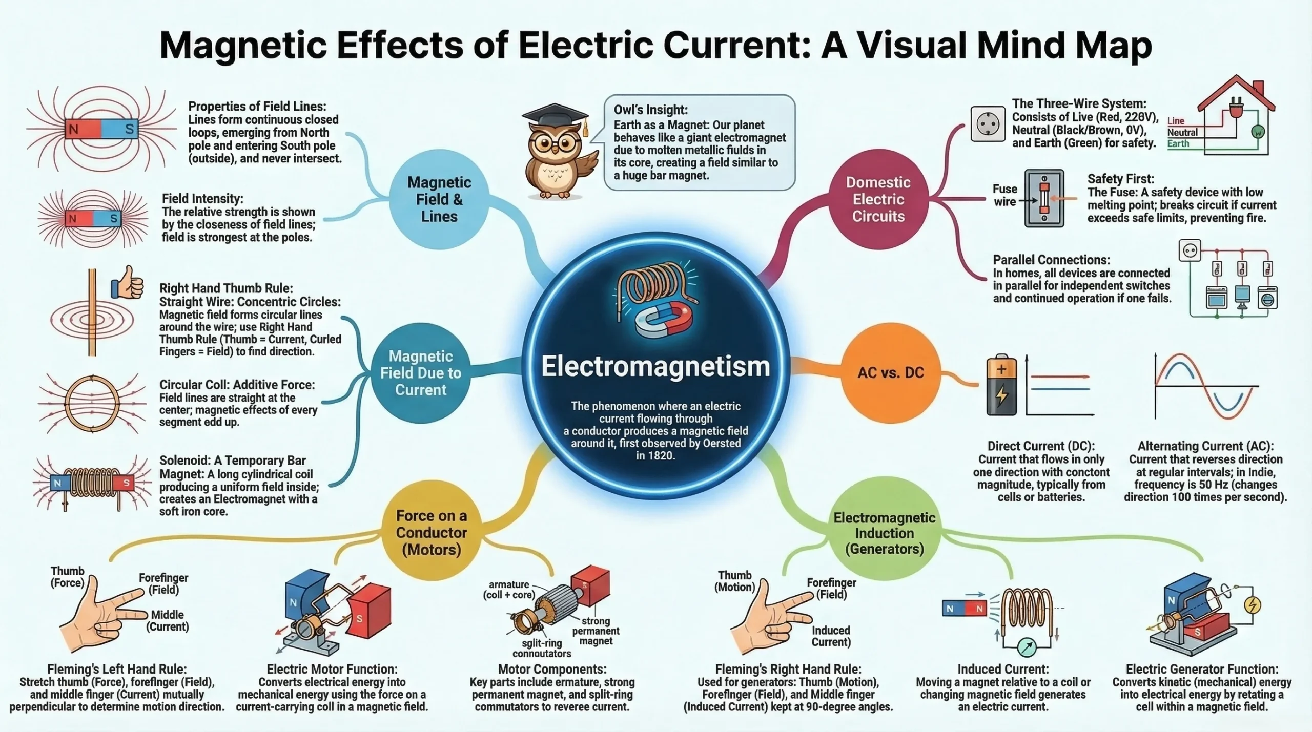
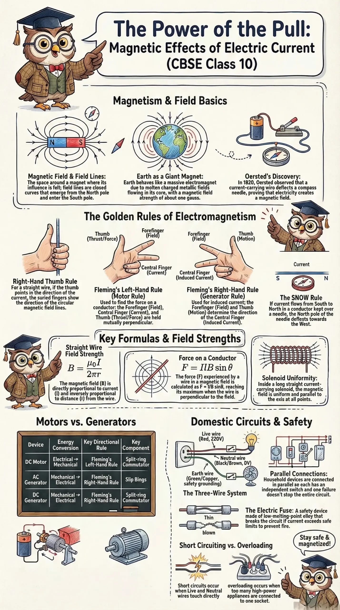
The Earth itself behaves as a huge magnet (or a giant solenoid). It is now widely accepted that Earth's magnetism arises from electric currents flowing through the molten charged metallic fluid in Earth's core a core with a radius of approximately 3,500 km (Earth's total radius ≈ 6,400 km). The strength of Earth's magnetic field is of the order of one gauss. The shape of Earth's magnetic field resembles that of a bar magnet of length one-fifth of Earth's diameter, buried at its centre.
CBSE Class 10 Physics Notes Magnetic Effects of Electric Current Revision Notes PDF
Fill the form to download this PDF
Magnetic Field and Magnetic Lines of Force
A magnetic field is the region or space surrounding a magnetic pole or magnet in which the magnetic effect can be experienced by another pole or magnet. It is a vector quantity it has both magnitude and direction.
Magnetic Lines of Force (Magnetic Field Lines)
A magnetic line of force is a line (straight or curved) in a magnetic field such that the tangent to it at any point gives the direction of the magnetic field at that point.
In simpler terms: if a free unit north pole (test pole) is placed in a magnetic field and is free to move, it will travel along the magnetic line of force in the direction of the field.
- From a north pole, field lines radiate outward.
- Toward a south pole, field lines converge inward.
- A small magnetic compass needle placed along a line of force always sets itself parallel to that line.
Properties of Magnetic Lines of Force
- Closed curves: All field lines form closed loops. Outside the magnet, they run from the north pole to the south pole. Inside the magnet, they run from the south pole to the north pole.
- Perpendicular at the magnet's surface: Magnetic lines of force are always perpendicular to the surface of the magnet at every point.
- Non-intersecting: Two magnetic lines of force never cross each other. If they did, a compass needle placed at the intersection point would have to point in two directions simultaneously - which is physically impossible.
- Density indicates field strength: Lines are crowded (closely spaced) near the poles where the field is strong, and spread out farther away where the field is weaker. The closer the field lines, the stronger the magnetic field.
- Intensity proportional to line density: The number of magnetic lines of force passing normally per unit area about a point gives the intensity (strength) of the magnetic field at that point.
Oersted's Experiment
Discovery of Electromagnetic Effect
- Romagnosi (1802) was the first to discover that electric current produces a magnetic effect.
- Hans Christian Oersted (1820) was the first to demonstrate this experimentally.
Oersted's Experimental Setup
A straight wire AB is connected in series with a battery (Ba) and a key (K). The wire is held horizontally in the north south direction above a magnetic compass needle.
Observations:
- When the key is closed (current flows), the north pole of the compass needle deflects towards the west.
- When the key is opened (current stops), the needle returns to its original N–S position.
- When the direction of current in the wire is reversed, the needle deflection is also reversed.
- When the wire is placed below the needle (with the same current direction), the deflection is reversed again.
- The amount of deflection depends on the distance of the needle from the wire closer means more deflection.
Conclusion: A current-carrying wire produces a magnetic field around itself. This relationship between electricity and magnetism is called electromagnetism. The magnetic effect of current is highly useful in electric motors, generators, telephones, and many other devices.
SNOW Rule
A mnemonic to relate current direction, conductor position, and needle deflection:
If current flows in the conductor from South towards North, with the conductor kept Over the needle, then the North pole of the needle will be deflected towards West.
Magnetic Field Due to a Straight Conductor and Circular Coil
Case 1: Straight Current → Circular Magnetic Field
When current flows through a straight wire, the magnetic field produced consists of circular lines of force centred on the wire, lying in planes perpendicular to the wire's length.
This can be demonstrated experimentally by sprinkling iron filings on a cardboard through which the wire passes — the filings arrange themselves in concentric circles around the wire.
Formula for Magnetic Field of a Straight Wire
B = μ0I/2πr
Where:
- B = magnetic field strength (in Tesla, T)
- μ₀ = permeability of free space (= 4π × 10⁻⁷ T·m/A)
- I = current (in Amperes, A)
- r = perpendicular distance from the wire (in metres, m)
Relationships:
- B is directly proportional to current (I) → more current = stronger field
- B is inversely proportional to distance (r) → further away = weaker field
Direction of Magnetic Field - Right Hand Thumb Rule (Maxwell's Corkscrew Rule)
Right Hand Thumb Rule:Imagine gripping the straight wire with your right hand, with the thumb pointing in the direction of conventional current. The curling of the fingers indicates the direction of the circular magnetic field lines around the wire.
This is also called Maxwell's Corkscrew Rule if a corkscrew is rotated in the direction of the current, the direction in which its handle turns gives the direction of the magnetic field.
- Current flowing vertically upward → magnetic field is anticlockwise (when viewed from above)
- Current flowing vertically downward → magnetic field is clockwise (when viewed from above)
Case 2: Circular Current → Straight Magnetic Field
When current flows through a circular coil (loop), the magnetic field at the centre of the coil consists of straight parallel lines lying in a plane perpendicular to the plane of the coil.
Each small segment of the circular coil is surrounded by magnetic lines of force, and at the centre all these lines add together, resulting in a stronger, uniform field.
Formula for Magnetic Field at Centre of a Circular Coil
B = μ0nI/2r
Where:
- n = number of turns in the coil
- I = current (A)
- r = radius of the coil (m)
Key relationships:
- B ∝ I (directly proportional to current)
- B ∝ 1/r (inversely proportional to radius)
- B ∝ n (directly proportional to number of turns)
Right Hand Thumb Rule (for circular coil):If the curled fingers of the right hand represent the direction of current in the circular wire, the outstretched thumb points in the direction of the magnetic field at the centre.
Magnetic Field Due to a Solenoid
What Is a Solenoid?
A solenoid is a long cylindrical coil formed by winding many turns of insulated copper wire over a hollow, non-conducting cylinder. It differs from a simple circular coil in that its length is much greater than its diameter.
A solenoid essentially behaves as a large number of circular coils stacked one behind the other along the same axis.
Magnetic Field of a Current-Carrying Solenoid
The magnetic field produced by a current-carrying solenoid closely resembles that of a bar magnet:
- Inside the solenoid: The magnetic field is uniform (the same at all points), represented by straight, parallel field lines along the axis.
- Outside the solenoid: The magnetic field is non-uniform.
- At the ends: Polarity exists one end acts as a north pole, the other as a south pole.
- Inside: Field lines run from south pole to north pole.
- Outside: Field lines run from north pole to south pole.
The current in each turn of the solenoid produces a magnetic field, and all these fields become additive, producing a strong, uniform field inside.
Polarity Rule for Solenoid Ends
- If the current in the coil at an end is clockwise (when viewed from that face) → that face is a South pole.
- If the current in the coil at an end is anticlockwise (when viewed from that face) → that face is a North pole.
(Mnemonic: S for South, S for clockwiSe; N for North, N for anti-clock-N-wise)
Formula for Magnetic Field Inside a Solenoid
B = μ0μrnI
Where:
- μ₀ = permeability of free space
- μᵣ = relative permeability of the core material
- n = number of turns per unit length
- I = current (A)
Factors affecting B:
| Factor | Relationship |
|---|---|
| Turns per unit length (n) | B ∝ n |
| Current (I) | B ∝ I |
| Core permeability (μᵣ) | B ∝ μᵣ |
Note: Permeability is a magnetic property of a material related to magnetism. A soft iron core dramatically increases μᵣ and hence B.
Difference Between Solenoid and Circular Coil Fields
| Feature | Solenoid | Circular Coil |
|---|---|---|
| Field inside | Uniform throughout most of the length | Non-uniform; varies with distance from centre |
| Field pattern | Straight, parallel lines along axis | Straight only at the centre |
| Decreases near ends? | Yes, slightly | Not applicable |
Electromagnets vs Permanent Magnets
What Is an Electromagnet?
An electromagnet is a temporary magnet consisting of many turns of insulated copper wire wound over a soft iron core (or horseshoe-shaped iron core). It produces a magnetic field only as long as electric current flows through the coil.
Factors Affecting Electromagnet Strength
- Number of turns in the coil: More turns → stronger electromagnet
- Magnitude of current: Strength is directly proportional to current (B ∝ I)
- Length of air gap between poles: Strength is inversely proportional to the gap between poles
- Core material: Soft iron with high μᵣ greatly enhances the field
Applications of Electromagnets
- Extracting bullets from the body (surgical electromagnets)
- Lifting heavy machines and scrap metal
- Electronic devices (relays, circuit breakers)
- MRI machines
Comparison: Electromagnet vs Permanent Magnet
| Feature | Electromagnet | Permanent Magnet |
|---|---|---|
| Magnetism type | Temporary (requires current) | Permanent |
| Field strength | Strong; adjustable | Relatively weak; fixed |
| Polarity reversal | Yes, by reversing current | Not possible |
| Demagnetisation | Stops when current stops | Difficult; requires heating or impact |
Do You Know?
- Hard steel, alnico (alloy of Al, Ni, Co, Fe) and Nipermag (alloy of Al, Fe, Ti) are used for permanent magnets.
- Soft iron is used for electromagnets (high permeability, easily magnetised and demagnetised).
- A steel rod can become a permanent magnet by placing it inside a solenoid carrying direct current.
- Permanent magnets are used in loudspeakers, galvanometers, voltmeters, ammeters, and speedometers.
- A permanent magnet can be demagnetised by heating it.
Force on a Current-Carrying Conductor in a Magnetic Field
Principle
A current-carrying conductor produces its own magnetic field. When placed in an external magnetic field, the two fields interact and a net mechanical force acts on the conductor.
Formula
For a conductor of length l carrying current I, placed in a magnetic field of intensity B, making an angle θ with the field:
F = BIl sin θ
Special cases:
- If θ = 90° (conductor perpendicular to field): F = BIl → maximum force
- If θ = 0° (conductor parallel to field): F = 0 → minimum/zero force
The force direction is perpendicular to the plane containing the conductor and the magnetic field.
Fleming's Left-Hand Rule
For finding the direction of force on a current-carrying conductor in a magnetic field.
Stretch the forefinger, middle finger, and thumb of the left hand mutually at right angles to each other. If the forefinger points in the direction of the magnetic Field, and the middle finger points in the direction of the Current, then the thumb gives the direction of the Force (motion/thrust).
Memory aid: Field → Forefinger | Current → Central finger | Thrust → Thumb
Factors Affecting the Force
| Factor | Relationship |
|---|---|
| Magnetic field strength (B) | F ∝ B |
| Current strength (I) | F ∝ I |
| Length of conductor (l) | F ∝ l |
Combined: F = BIl (for θ = 90°)
SI Unit of Magnetic Field Strength
B = F/Il
1 Tesla (T) = 1 N A⁻¹ m⁻¹
That is, 1 Tesla is the field strength when a conductor of 1 metre length carrying 1 Ampere of current experiences a force of 1 Newton.
Electromagnetic Induction
Electromagnetic induction is the phenomenon by which an electric current is induced in a circuit due to a changing magnetic field (or changing magnetic flux) linked with that circuit.
In essence, electromagnetic induction means production of electricity from magnetism — the reverse of electromagnetism.
- The induced electric current is called induced current.
- The e.m.f. that drives this current is called induced e.m.f.
Demonstration
When a straight metallic wire is moved up and down between the poles of a horseshoe magnet, the magnetic flux linked with the wire changes. A galvanometer connected across the wire shows a deflection indicating that current is produced. This current exists only as long as the wire is moving (i.e., only when flux is changing).
Faraday's Discovery (1831)
Michael Faraday discovered electromagnetic induction in 1831 through two key experiments:
Experiment 1 (Moving Magnet):
- When the north pole of a magnet was moved toward a coil → galvanometer deflected to the right (current induced).
- When the magnet was kept stationary inside the coil → galvanometer showed zero deflection.
- When the magnet was moved away → galvanometer deflected to the left.
- Conclusion: Current flows only when the magnet is in motion relative to the coil.
Experiment 2 (Changing Current in Primary Coil):
- A primary coil P was placed near secondary coil AB. When the key of the primary circuit was pressed (circuit closed), the galvanometer deflected right.
- When the key was held pressed (steady current), deflection returned to zero.
- When the key was released (circuit opened), deflection was to the left.
- Conclusion: The changing current in the primary creates a changing magnetic flux, which induces current in the secondary just like a moving magnet.
Factors Affecting Induced Current
- Number of turns in the coil: More turns → larger induced current.
- Strength of the magnet: A stronger magnet produces larger induced current.
- Speed of magnet movement: A faster-moving magnet produces larger induced current.
Fleming's Right-Hand Rule
For finding the direction of induced current.
Stretch the thumb, forefinger, and middle finger of the right hand mutually at right angles. If the forefinger represents the direction of the magnetic Field, and the thumb represents the direction of Motion of the conductor, then the middle finger gives the direction of the induced Current.
Memory aid: Field → Fore finger | Motion → thuMb | Current → Central finger
Direct Current and Alternating Current
Direct Current (DC)
DC is a current that has a constant magnitude and flows in the same direction at all times through a circuit.
- Generated by cells and batteries.
- Current always flows from higher potential (positive terminal) to lower potential (negative terminal).
Alternating Current (AC)
AC is a current that periodically changes both its magnitude and direction at regular intervals.
- Frequency of household AC in India: 50 Hz (50 cycles per second).
- This means AC changes direction 100 times per second (direction reverses twice per cycle).
- AC changes direction after each half-rotation of the generator coil.
Advantages of AC over DC
| Advantage |
|---|
| Can be transmitted over long distances with minimal energy loss |
| Cheaper and easier to produce |
| Voltage can be stepped up or stepped down using a transformer |
| Transmitting at high voltage & low current reduces line losses |
| AC motors and appliances are simpler to operate |
| Can be easily converted to DC when needed |
Disadvantages of AC over DC
| Disadvantage |
|---|
| AC attracts a person who touches a live wire; DC gives a repelling shock |
| AC shock is sudden, severe, and potentially fatal |
| Skin effect — AC flows over the conductor surface, increasing effective resistance |
| Commercial generators do not produce pure AC |
| Applications like electroplating and battery charging require DC |
Transformer
A transformer is a device that uses electromagnetic induction to change (step up or step down) AC voltage. It consists of two coils (primary and secondary) wound around a soft iron core. Transformers are critical in transmitting electricity over long distances with minimum power loss.
Electric Motor and Generator
Energy Conversions
| Device | Energy Conversion |
|---|---|
| Electric Motor | Electrical energy → Mechanical (kinetic) energy |
| Electric Generator | Mechanical (kinetic) energy → Electrical energy |
DC Motor
Principle: A current-carrying conductor in a magnetic field experiences a force (Fleming's Left-Hand Rule). This force is used to produce rotational motion.
Construction
- Armature: A coil of many turns of insulated copper wire wound over a soft iron core; fixed on the shaft between poles of a strong magnet.
- Commutator: A split-ring commutator (the ring split into two halves C₁ and C₂); rotates with the coil.
- Brushes: Two carbon brushes (B₁ and B₂) press against the commutator halves; connected to the DC source (battery).
Working
- Brush B₁ connects to the positive terminal; B₂ to the negative terminal.
- Current flows through the coil in the direction A→B→C→D.
- By Fleming's Left-Hand Rule, arm AB experiences a downward force and arm CD an upward force → coil rotates anticlockwise.
- After half a rotation, the commutator halves swap brushes → current in the coil reverses to D→C→B→A.
- The forces on the arms reverse accordingly, but the coil continues to rotate in the same anticlockwise direction.
Role of the commutator: It reverses the current direction in the coil every half-rotation, ensuring continuous rotation in one direction. Without the commutator, the coil would oscillate back and forth rather than rotate continuously.
DC Generator (Dynamo)
Principle: A coil rotating in a magnetic field experiences a changing magnetic flux, which induces an EMF (Fleming's Right-Hand Rule).
Construction
Very similar to a DC motor: armature coil + strong magnet + split-ring commutator + carbon brushes + external terminals P and Q.
Working
- The shaft (and coil) is rotated mechanically (by steam, water, wind, or a diesel engine).
- As the coil rotates, the arms cut through magnetic field lines → EMF is induced.
- In Figure (a): arm AB moves downward; current flows D→C→B→A; current in external circuit from P→Q.
- After half a rotation, arm AB moves upward; current flows A→B→C→D; but the commutator swap keeps external current still from P→Q.
- A constant-direction (direct) current flows in the external circuit.
AC Generator (Alternator)
Difference from DC Generator: The split-ring commutator is replaced by two cylindrical slip rings (C₁ and C₂).
Construction:
Armature coil wound over soft iron core + strong magnet + two slip rings (each permanently connected to one end of the coil) + carbon brushes + fixed terminals P and Q.
Working:
- As the coil rotates, current in arm AB reverses every half-rotation.
- Because the slip rings are permanently connected (unlike a split commutator, which swaps), the direction of current in the external circuit also reverses every half-rotation.
- Result: An alternating current flows through the connected device.
Most power-generating stations worldwide use AC generators due to the ease of stepping up voltage with transformers for long-distance transmission.
Domestic Electric Circuits
Supply from Power Stations
Electricity generated at power stations is delivered to homes via overhead poles or underground cables using two thick aluminium wires.
Main Board (Distribution Board)
Located outside the building (veranda or porch), it contains:
- Energy meter measures electrical energy consumed
- Main switch disconnects entire supply
- Fuse (F) placed in the path of the live wire
Three Wires in Household Supply
| Wire | Colour | Potential |
|---|---|---|
| Live wire (L) | Red | 220 V |
| Neutral wire (N) | Black (or Brown) | 0 V |
| Earth wire (E) | Green (bare copper) | 0 V (connected to earth plate) |
The earth wire is a thick bare copper wire connected to a copper plate buried in moist earth. It provides a safe discharge path in case of electrical faults.
Inside the Building
All devices inside a house are connected in parallel each with its own independent switch and fuse. This ensures:
- Every device receives the same voltage (220 V).
- A fault in one circuit does not affect others.
- Individual devices can be switched on/off independently.
Electric Fuse
An electric fuse is a safety device a thin wire of copper, aluminium, or tin-lead alloy with a low melting point. When current exceeds the safe limit, the fuse wire heats up and melts, breaking the circuit and preventing damage to appliances and fire.
Function of Earth Wire
If the insulation of internal wires wears away over time, the live wire may contact the metallic body of an appliance. Without earthing, touching the appliance causes an electric shock. The earth wire keeps the appliance's body at zero potential, preventing shocks.
Use of Switch
- All switches are connected to the live wire.
- Switching off disconnects the appliance from the live wire.
- If the switch were on the neutral wire, the appliance would remain connected to the live wire even when off, posing a shock hazard.
Short Circuit
A short circuit occurs when the live wire and neutral wire come into direct contact (due to damaged insulation or appliance fault).
- Circuit resistance drops to near zero.
- Current increases to a dangerously large value.
- Enormous heat is generated → circuit can catch fire.
- A fuse in the circuit melts and breaks the circuit, preventing fire.
Overloading
Overloading occurs when too many high-power appliances (geysers, heaters, refrigerators) are connected to the same socket or circuit, drawing a combined current beyond the circuit's safe rating. The resulting excessive current produces dangerous heat and can cause fire.
Magnetic Effects of Electric Current Chapter 12 Solved Examples
Q: What is the magnetic field at a distance of 5 cm from a straight wire carrying a current of 10 A?
Solution:
B = μ0I/2πr = 4π x 10-7 x 10 ⁄ 2πr x 0.05
B = 4π x 10-6/ 0.01 = 4 x 10 -5 T
B = 4 × 10⁻⁵ T
Q: If the current in a straight wire is doubled, what happens to the magnetic field at a fixed distance?
Solution: Since B ∝ I, doubling the current doubles the magnetic field.
The magnetic field becomes twice its original value.
Q: Current flowing in conductor A is 2 A and in conductor B is 4 A. What is the ratio of magnetic fields around A to B at a distance of 10 cm from each?
Solution: BA/BB = IA/IB = 2/4 = 1/2
B_A : B_B = 1 : 2
Q: The current in two conductors A and B is the same. What is the ratio of the magnetic field around conductor A at 5 cm to that around conductor B at 2 cm?
Solution: Since B ∝ 1/r (at constant I):
BA/BB = rB/RA = 2/5 = 0.4
The ratio B_A : B_B = 0.4 (i.e., 2:5)
Q: A circular coil has 50 turns, carries a current of 2 A, and has a radius of 10 cm. Calculate the magnetic field at its centre. (μ₀ = 4π × 10⁻⁷ T·m/A)
Solution:
B = u0nI/2r = 4π x 10-7 x 50 x 2 / 2x0.1
B = 4π x 10-7 x 100 / 0.2 = 4π x 10-5 / 0.2 = 2π x 10-4
B ≈ 6.28 × 10⁻⁴ T
Q: A conductor of length 0.5 m carries a current of 3 A and is placed perpendicular to a magnetic field of 0.4 T. What force acts on it?
Solution:
F = BIl sin θ = 0.4 x 3 x 0.5 x sin 900 = 0.6 x 1 = 0.6 N
F = 0.6 N
Q: A conductor carrying 5 A and of length 2 m is placed parallel to a magnetic field of 0.3 T. What is the force on it?
Solution: When the conductor is parallel to the field, θ = 0°, sin 0° = 0.
F = BIl sin 00 = 0
F = 0 (no force acts)
Q: A conductor experiences a force of 1.2 N when carrying 2 A in a magnetic field perpendicular to it. The conductor's length is 0.3 m. What is the magnetic field strength?
Solution:
B = F/Il = 1.2/2x0.3 = 1.2/0.6 = 2T
B = 2 T
Q: If the magnetic field strength at a point is B and the current is doubled, what is the new magnetic field?
Solution: B ∝ I, so doubling I doubles B.
New magnetic field = 2B
Q: State the direction of magnetic field when current in a straight vertical wire flows upward.
Solution: Apply the Right Hand Thumb Rule thumb points upward (direction of current); fingers curl anticlockwise when viewed from above.
The magnetic field is anticlockwise when viewed from above (from the top of the wire).
Q: At which face of a solenoid does the north pole appear?
Solution: Apply the polarity rule: if the current flows anticlockwise when viewed from a face, that face is the North pole.
The face where the current flows anticlockwise acts as the North pole.
Q: What is the SI unit of magnetic field strength, and how is it defined?
Solution: B = F/Il
1 Tesla = 1 N A⁻¹ m⁻¹. It is the magnetic field strength when a conductor of 1 m length carrying 1 A of current perpendicular to the field experiences a force of 1 N.
SI unit is Tesla (T); 1 T = 1 N A⁻¹ m⁻¹
Q: Why does a compass needle deflect when placed near a current-carrying wire?
Solution: The current-carrying wire produces a magnetic field around itself. The compass needle, being a tiny magnet, responds to this field and deflects in its direction.
The magnetic field produced by the current exerts a force on the compass needle, causing it to deflect.
Q: When is the current induced in a closed coil placed near a magnet?
Solution: Current is induced only when the magnetic flux through the coil is changing, i.e., when the magnet is in motion relative to the coil (moving toward or away). When the magnet is stationary, flux does not change and no current is induced.
Current is induced only when the magnet is in motion relative to the coil.
Q: Why is a soft iron core used in electromagnets instead of steel?
Solution: Soft iron has high magnetic permeability (μᵣ) and is easily magnetised and demagnetised. Steel retains magnetism (making it a permanent magnet), which is unsuitable for electromagnets that need to be switched on and off.
Soft iron allows easy magnetisation and demagnetisation, making it ideal for electromagnets.
Q: What is the role of the commutator in a DC motor?
Solution: The commutator reverses the direction of current in the coil every half-rotation. This ensures the force on each arm of the coil always acts in the same rotational direction, enabling continuous rotation of the coil/shaft.
The commutator ensures unidirectional rotation by reversing the current direction after every half-rotation.
Q: How does an AC generator differ from a DC generator in construction?
Solution: An AC generator uses slip rings (two cylindrical rings permanently connected to the coil ends), while a DC generator uses a split-ring commutator (two halves of a split ring). The slip rings allow the current to reverse every half-rotation, producing AC, whereas the commutator maintains current in one direction, producing DC.
AC generator uses slip rings; DC generator uses a split-ring commutator.
Q: The frequency of AC in India is 50 Hz. How many times per second does the current change direction?
Solution: In 50 Hz AC, there are 50 complete cycles per second. In each cycle, the current changes direction twice (once from + to and once from to +).
Direction changes per second = 50 \times 2 = 100
The current changes direction 100 times per second.
Q: Why are household connections made in parallel and not in series?
Solution: Parallel connections ensure each device receives the same voltage (220 V) regardless of other devices. Each device also has an independent switch and fuse. If one device fails, others continue to function. In a series connection, all would share the voltage and a single fault would break the entire circuit.
Parallel connections provide same voltage to each device, independent control, and prevent one device's failure from affecting others.
Q: What is a short circuit and why is it dangerous?
Solution: A short circuit occurs when the live and neutral wires make direct contact, reducing circuit resistance to near zero. By Ohm's law (I = V/R), the current becomes enormously large. This massive current heats the wires rapidly and can cause fire. A fuse melts under this condition, breaking the circuit and preventing damage.
In a short circuit, resistance drops to zero → very large current flows → excessive heat → risk of fire. A fuse protects the circuit by melting and breaking it.
Magnetic Effects of Electric Current Quick Revision Formulas and Facts
| Concept | Formula / Fact |
|---|---|
| Magnetic field of straight wire | B = μ₀I / (2πr) |
| Magnetic field of circular coil (centre) | B = μ₀nI / (2r) |
| Magnetic field inside solenoid | B = μ₀μᵣnI |
| Force on conductor in field | F = BIl sinθ |
| Definition of 1 Tesla | 1 T = 1 N A⁻¹ m⁻¹ |
| Max force (θ = 90°) | F = BIl |
| Zero force (θ = 0°) | F = 0 |
| AC frequency in India | 50 Hz; changes direction 100 times/s |
| Household voltage in India | 220 V (live wire); 0 V (neutral wire) |
| Like poles | Repel each other |
| Unlike poles | Attract each other |
| Oersted's discovery year | 1820 |
| Faraday's discovery year | 1831 |
| DC motor principle | F on current-carrying conductor in B field |
| AC generator key feature | Slip rings (unlike DC generator's commutator) |
| Fuse wire property | Low melting point |
| Short circuit effect | Near-zero resistance → huge current → fire |
| Overloading | Too many appliances → current exceeds safe limit |
Magnetic Effects of Electric Current Important Rules Summary
| Rule | Direction Determined |
|---|---|
| Right Hand Thumb Rule | Magnetic field direction around current-carrying conductor |
| Maxwell's Corkscrew Rule | Same as Right Hand Thumb Rule |
| Polarity Rule (Solenoid) | Clockwise current → South pole; Anticlockwise → North pole |
| Fleming's Left-Hand Rule | Force on current-carrying conductor in magnetic field (motor) |
| Fleming's Right-Hand Rule | Direction of induced current (generator) |
| SNOW Rule | Relation between current direction, conductor position, needle deflection |