Light is one of the most important topics in Class 10 Science, and it helps us understand how we see objects around us. The chapter Light Reflection and Refraction Class 10 explains how light travels, how it changes direction, and how images are formed by mirrors and lenses. In these light reflection and refraction Chapter 9 class 10 notes, students learn the basic ideas of reflection of light, refraction of light, spherical mirrors, lenses, and the human eye in a simple and clear way.
These light reflection and refraction class 10 notes NCERT solutions are designed to help students understand the concepts step-by-step. When light falls on a surface, it may bounce back, which is called reflection, or it may bend when it passes from one medium to another, which is called refraction. These concepts are very important for understanding devices like mirrors, spectacles, microscopes, and cameras.
Students often look for class 10 light reflection and refraction notes PDF to revise the chapter quickly before exams. These notes also include key formulas, ray diagrams, and important definitions that make learning easier. Along with theory, light reflection and refraction class 10 questions and answers help students practice and test their understanding of the chapter.
Nature of Light
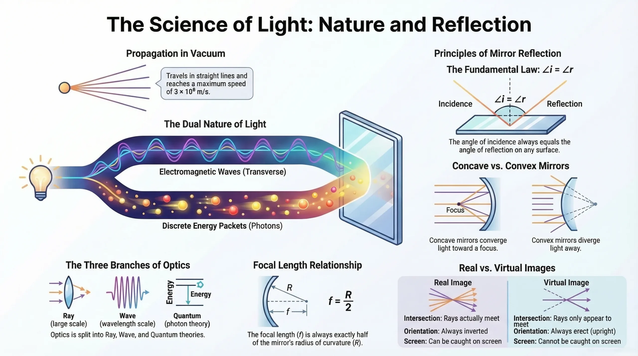
Light is a fascinating physical phenomenon that has been studied and debated for centuries. Modern physics recognises its dual nature it behaves as both a wave and a particle depending on the experimental context.
Newton's Corpuscular Theory (Particle Nature)
Isaac Newton proposed that light travels as a stream of extremely small, fast-moving particles called corpuscles. This theory successfully explained reflection and refraction but failed to account for interference and diffraction.
Huygens' Wave Theory
Christian Huygens proposed that light propagates as mechanical waves requiring a medium (hypothetical "ether"). This was later refined: light waves are electromagnetic in nature and require no medium to travel. They can propagate through vacuum at a maximum speed of 3 × 10⁸ m/s.
Wave theory explained interference and diffraction but failed to explain the photoelectric effect.
Planck's Quantum Theory
Max Planck introduced the concept of photons discrete energy packets (quanta) of light. Each photon carries energy:
E = hν
Where:
- h = Planck's constant = 6.6 × 10⁻³⁴ J·s
- ν = frequency of light
Einstein used quantum theory to explain the photoelectric effect, earning the Nobel Prize.
De Broglie's Dual Nature
Louis de Broglie reconciled the two views: light exhibits both wave nature (interference, diffraction, polarisation) and particle nature (photoelectric effect, Compton effect). This is known as the wave-particle duality of light.
| Theory | Explains | Fails to explain |
|---|---|---|
| Newton's Corpuscular | Reflection, Refraction | Interference, Diffraction |
| Huygens' Wave Theory | Interference, Diffraction | Photoelectric effect |
| Planck's Quantum Theory | Photoelectric effect | Interference, Diffraction |
| De Broglie's Dual Nature | All phenomena | — |
CBSE Class 10 Physics Notes - Light, Reflection, and Refraction Revision Notes PDF
Fill the form to download this PDF
Properties of Light
- Light travels in straight lines (rectilinear propagation).
- Its speed in vacuum/air is maximum: 3 × 10⁸ m/s (more precisely, 297,489,978 m/s).
- Light does not require a material medium it travels through vacuum.
- It exhibits reflection, refraction, interference, diffraction, polarisation, and double refraction.
- Luminous objects emit their own light (e.g., sun, stars, lamps).
- Non-luminous objects are visible only through scattered/reflected light (e.g., moon, books, trees).
- Human eyes are most sensitive to yellow light and least sensitive to violet and red. This is why commercial vehicles are painted yellow and sodium vapour lamps are used in street lighting.
Types of Medium
| Medium | Description | Examples |
|---|---|---|
| Transparent | Light travels freely over large distances | Glass, water, air |
| Opaque | Light cannot pass through | Metals, wood, paper |
| Translucent | Light passes partially; intensity reduces quickly | Fog, butter paper |
Propagation of Light
Ray of Light
A straight line showing the direction of travel of light is called a ray of light.
Beam of Light
A collection (bundle) of light rays is called a beam of light. Beams can be:
- Divergent — rays spread outward from a point
- Convergent — rays meet at a point
- Parallel — rays travel side by side
Reflection of Light
When light rays fall on a polished surface and bounce back into the same medium, the phenomenon is called reflection of light.
Terms
- Incident ray — the ray that strikes the reflecting surface
- Reflected ray — the ray that bounces back from the surface
- Normal — a line perpendicular to the reflecting surface at the point of incidence
- Angle of Incidence (i) — angle between incident ray and normal
- Angle of Reflection (r) — angle between reflected ray and normal
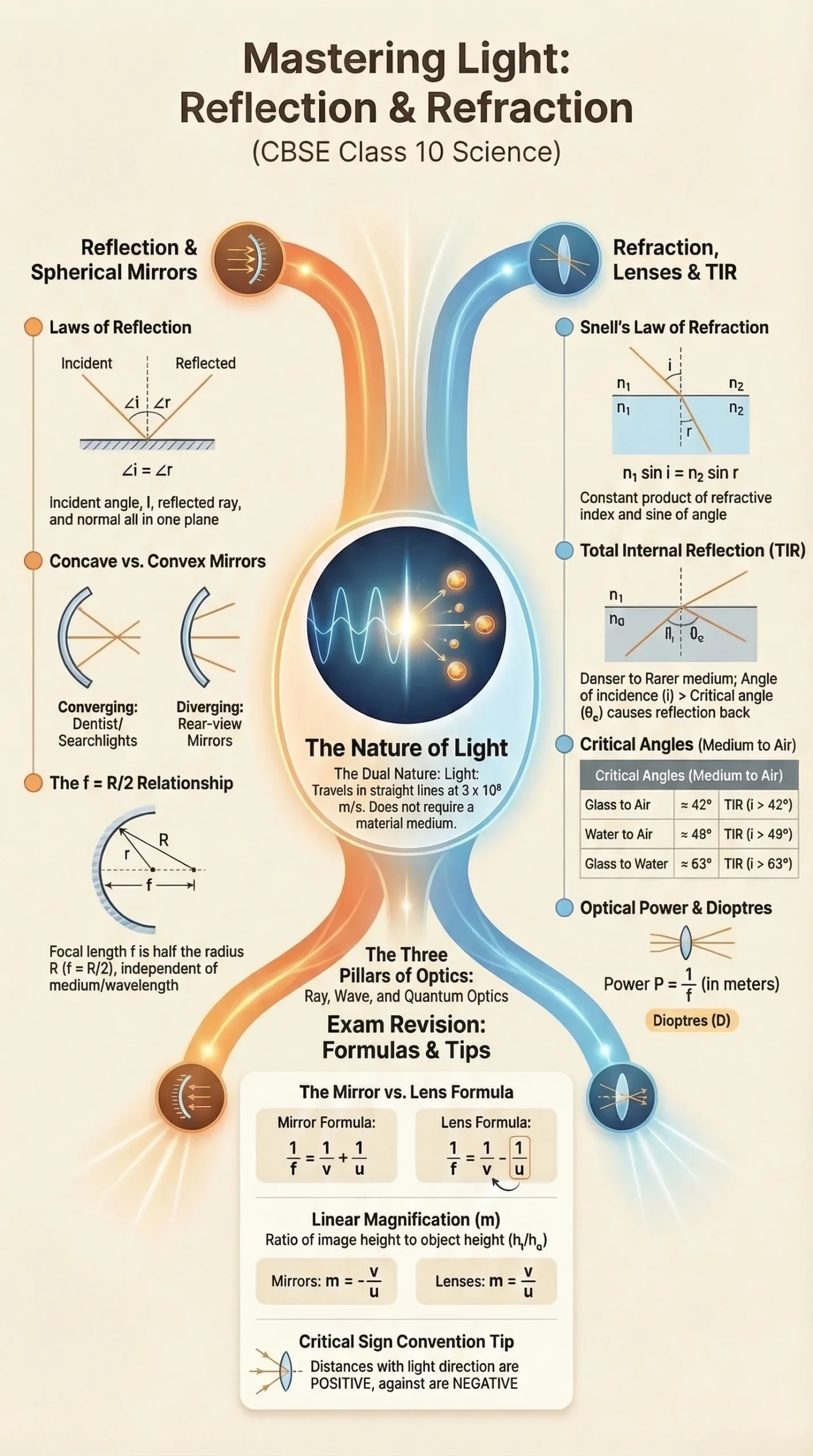
Laws of Reflection
- The incident ray, reflected ray, and the normal at the point of incidence all lie in the same plane.
- The angle of incidence equals the angle of reflection: ∠i = ∠r
These laws apply to all types of reflecting surfaces plane and spherical.
Types of Reflection
| Regular (Specular) Reflection | Irregular (Diffuse) Reflection |
|---|---|
| Occurs on smooth, polished surfaces (mirrors) | Occurs on rough surfaces |
| Reflected rays are parallel | Rays scatter in all directions |
| Forms clear images | No distinct image formed |
Plane Mirrors
A plane mirror is a highly polished flat (plane) surface. One side of a flat glass plate is coated with silver or nickel, making it reflective.
Properties of Image Formed by a Plane Mirror
- Virtual — cannot be obtained on a screen
- Erect — upright (not inverted)
- Same size as the object
- Formed behind the mirror, at the same distance as the object is in front
- Laterally inverted — left and right are swapped
Lateral Inversion vs. Inversion
- Inversion: image turns 180° about a horizontal axis (upside down)
- Lateral inversion: image turns 180° about a vertical axis (left-right swap)
Multiple Images in Inclined Mirrors
When two plane mirrors are inclined at angle θ to each other, the number of images n formed is:
- If 360°/θ is even: n = (360/θ) − 1
- If 360°/θ is odd and object is symmetrically placed: n = (360/θ) − 1
- If 360°/θ is odd and object is asymmetrically placed: n = 360/θ
- If mirrors are parallel (θ = 0°): n = ∞
Example: θ = 60° → n = (360/60) − 1 = 5 images
Deviation by Plane Mirror
A plane mirror deviates light by: δ = 180° − 2i
Maximum deviation = 180° (at normal incidence, i = 0°)
Important Points
- Focal length of plane mirror = infinity
- Power of plane mirror = zero
- If mirror rotates by angle θ, reflected ray rotates by 2θ
- After reflection: speed, wavelength, and frequency remain unchanged, amplitude/intensity changes
Spherical Mirrors: Concave and Convex
A spherical mirror is a mirror whose reflecting surface forms part of a hollow sphere.
Types
| Feature | Concave Mirror | Convex Mirror |
|---|---|---|
| Reflecting surface | Inner hollow surface | Outer bulging surface |
| Nature | Converging | Diverging |
| Image (generally) | Real and inverted (for real objects beyond F) | Virtual and erect |
| Use | Shaving mirror, doctor's torch, headlights | Rear-view mirror, street light reflectors |
Important Terminology
| Term | Definition |
|---|---|
| Pole (P) | Centre of the spherical mirror |
| Centre of curvature (C) | Centre of the hollow sphere of which the mirror is a part |
| Radius of curvature (R) | Radius of the hollow sphere |
| Principal axis | Line passing through C and P |
| Principal focus (F) | Point where parallel rays converge (concave) or appear to diverge from (convex) after reflection |
| Focal length (f) | Distance between pole P and focus F, f = R/2 |
| Aperture | Effective width of the mirror |
Rules for Drawing Ray Diagrams (Concave Mirror)
- A ray parallel to the principal axis → reflects through focus F
- A ray through focus F → reflects parallel to principal axis
- A ray through centre of curvature C → retraces its own path
- A ray at pole → reflects symmetrically about the principal axis (∠i = ∠r)
Image Formation by Concave Mirror
| Object Position | Image Position | Nature of Image |
|---|---|---|
| At infinity | At F | Real, inverted, highly diminished |
| Between ∞ and C | Between F and C | Real, inverted, smaller |
| At C | At C | Real, inverted, same size |
| Between C and F | Between C and ∞ | Real, inverted, enlarged |
| At F | At infinity | Real, inverted, infinitely large |
| Between F and P | Behind the mirror | Virtual, erect, enlarged |
Image Formation by Convex Mirror
| Object Position | Image Position | Nature |
|---|---|---|
| At infinity | At F (behind mirror) | Virtual, erect, highly diminished |
| Anywhere in front | Between P and F (behind mirror) | Virtual, erect, diminished |
Convex mirror always forms virtual, erect, and diminished images making it ideal as a rear-view mirror (wider field of view than plane mirror).
Real vs Virtual Image
| Real Image | Virtual Image |
|---|---|
| Formed by actual intersection of rays | Formed where rays appear to diverge from |
| Can be obtained on screen | Cannot be obtained on screen |
| Always inverted | Always erect |
| In front of mirror | Behind the mirror |
Mirror Formula and Magnification
Mirror Formula
1/f = 1/u + 1/v
Where:
- u = object distance from pole (negative for real objects)
- v = image distance from pole
- f = focal length
Also: R = 2f and f = R/2
Sign Convention
- Distances measured from the pole
- Direction of incident light → positive
- Opposite to incident light → negative
- Heights above principal axis → positive
- Heights below principal axis → negative
Linear Magnification
m = -v/u = hi/ho = f/f-u = f-v/f
- m is negative → real, inverted image
- m is positive → virtual, erect image
- |m| > 1 → enlarged; |m| < 1 → diminished, |m| = 1 → same size
Power of a Mirror
P = -1/f(m) =-100/f(cm)
Power of a plane mirror = 0 dioptres
Refraction of Light
Refraction is the bending of light as it passes from one medium to another, caused by a change in its velocity.
- Speed of light is maximum in vacuum (3 × 10⁸ m/s)
- Speed is less in denser media
Laws of Refraction (Snell's Law)
- The incident ray, refracted ray, and normal at the point of incidence all lie in the same plane.
- Snell's Law: μ₁ sin i = μ₂ sin r = constant
Where μ is the refractive index of the medium.
Relative Refractive Index
1μ2 = μ2/μ1 = ν1/v2
When medium 1 is air: it becomes the absolute refractive index.
Bending of Light
| Transition | Behaviour |
|---|---|
| Rarer → Denser | Ray bends towards the normal (∠i > ∠r) |
| Denser → Rarer | Ray bends away from the normal (∠i < ∠r) |
Key fact: Refractive index is maximum for violet light and minimum for red light.
Apparent Depth and Normal Shift
When an object in a denser medium is viewed from a rarer medium:
dapparent = dactual/μ
Normal shift: x =- dac (1-1/μ)
This is why objects submerged in water appear shallower than they really are.
Lateral Shift through a Glass Slab
d = t/cos r sin(i - r)
Where t = thickness of the slab.
Total Internal Reflection (TIR)
When light travels from a denser to a rarer medium and the angle of incidence exceeds the critical angle (θc), light does not refract it is entirely reflected back into the denser medium.
Conditions for TIR
- Light must travel from denser → rarer medium
- Angle of incidence > critical angle (i > θc)
Critical Angle Formula
sin θc = μR/μD= 1/μ
| Transition | Critical Angle |
|---|---|
| Glass → Air | ~42° |
| Water → Air | ~49° |
| Glass → Water | ~63° |
Applications of TIR
| Application | Explanation |
|---|---|
| Sparkling of diamonds | Refractive index of diamond = 2.5; θc = 24°. Cutting ensures i > θc, causing repeated TIR and brilliant sparkle |
| Optical fibres | Light undergoes multiple TIR along the core (higher μ) surrounded by cladding (lower μ), transmitting data with zero loss |
| Mirage | In deserts, air near hot ground has lower μ. Light from distant objects undergoes TIR, creating an illusion of water |
| Looming | In polar regions, μ decreases with height, causing TIR and apparent elevation of objects |
TIR produces 100% reflection no intensity loss. This is why TIR-based images are brighter than those from mirrors or lenses.
Lenses - Convex and Concave
A lens is a transparent optical element bounded by two curved surfaces (or one curved and one plane).
Types of Lenses
| Convex (Converging) Lens | Concave (Diverging) Lens |
|---|---|
| Thicker at centre | Thinner at centre |
| Converges parallel rays | Diverges parallel rays |
| Positive focal length | Negative focal length |
Subtypes include: bi-convex, plano-convex, concavo-convex (convex), bi-concave, plano-concave, convexo-concave (concave)
Terms
- Optical Centre (O) — point through which any ray passes undeviated
- Principal Axis — line through the optical centre perpendicular to the lens
- First Principal Focus (F₁) — object point for which the image forms at infinity
- Second Principal Focus (F₂) — image point when object is at infinity (used for focal length convention)
- Focal Length (f) — distance from optical centre to F₂
- Aperture — effective diameter; image intensity ∝ (aperture)²
Rules for Image Formation (Thin Lens)
- Ray through optical centre → passes undeviated
- Ray through/towards first focus → emerges parallel to principal axis
- Ray parallel to principal axis → passes through (or appears to pass through) second focus F₂
Image Formation by Convex Lens
| Object Position | Image Position | Nature |
|---|---|---|
| At infinity | At F₂ | Real, inverted, highly diminished |
| Between ∞ and 2F | Between F and 2F | Real, inverted, diminished |
| At 2F | At 2F | Real, inverted, same size |
| Between 2F and F | Between 2F and ∞ | Real, inverted, enlarged |
| At F | At infinity | Real, inverted, infinitely large |
| Between F and O | On same side as object | Virtual, erect, enlarged |
Image Formation by Concave Lens
| Object Position | Image Position | Nature |
|---|---|---|
| At infinity | At F (same side as object) | Virtual, erect, highly diminished |
| Anywhere in front | Between F and O | Virtual, erect, diminished |
A concave lens always forms a virtual, erect, diminished image regardless of object position.
Lens Formula, Power, and Magnification
Lens Formula
1/f = 1/v - 1/μ
Lensmaker's Formula
1/f = (μlens / μmedium - 1) (1/R1 - 1/R2)
Focal length depends on: refractive index, radii of curvature R₁ and R₂, and wavelength (colour) of light.
Magnification of a Lens
M = h1/ho = v/u
Power of a Lens
P = 1/f(in metres)
Unit: Dioptre (D)
Combination of Lenses
In contact:
1/F = 1/f1 + 1/f2, P = P1 + P2
Separated by distance d:
1/F = 1/f1 + 1/f2 - d/f1f2, P = P1+ P2 - dP1P2
Sign Summary for Lenses
| Quantity | Real Image | Virtual Image |
|---|---|---|
| u | − | − |
| v | + | − |
| h₁ (object height) | + | + |
| h₂ (image height) | − | + |
| m | − | + |
Class 10 Chapter 9 Light, Reflection, and Refraction Solved Examples
Q: An object is placed in front of a plane mirror. If the mirror is moved away from the object by distance x, by how much does the image move?
Solution:
- Initial object distance = d; image is also at distance d behind mirror
- After mirror shifts by x: new object distance = d + x; new image distance = d + x behind mirror
- Original image position from object = 2d
- New image position from object = 2(d + x)
- Image moves by 2x
Q: A man 2 m tall with eye level at 1.84 m wants to see his full image. What is the minimum mirror length?
Solution:
- To see head (H): mirror segment AC = ½ × HE = ½ × (2 − 1.84) = 0.08 m
- To see feet (F): mirror segment BC = ½ × EF = ½ × 1.84 = 0.92 m
- Minimum mirror length = 0.08 + 0.92 = 1 m
Q: Two plane mirrors are inclined so a ray parallel to the second mirror reflects from it parallel to the first. Find the angle between them.
Solution:
- Let angle between mirrors = θ
- Using geometry in triangle OBC: 3θ = 180°
- θ = 60°
Q: Find image position, nature, and magnification when object is 10 cm in front of a concave mirror of R = 15 cm.
Solution:
- f = −R/2 = −7.5 cm, u = −10 cm
- 1/v = 1/f − 1/u = 1/(−7.5) − 1/(−10) = −2.5/30 = −1/30 × 2.5
- v = −30 cm (real image, 30 cm in front)
- m = −v/u = −(−30)/(−10) = −3 (real, inverted, 3× magnified)
Q: Object is 5 cm in front of same concave mirror (f = −7.5 cm).
Solution:
- 1/v = 1/(−7.5) − 1/(−5) = 1/15
- v = +15 cm (virtual image, 15 cm behind mirror)
- m = −(+15)/(−5) = +3 (virtual, erect, 3× magnified)
Q: Jogger approaches at 5 m/s. How fast does the image move when jogger is 39 m away?
Solution:
- f = +1 m, u = −39 m → v = fu/(u−f) = 1 × (−39)/(−39−1) = 39/40 m
- After 1 s: u = −34 m → v′ = 34/35 m
- Image displacement = 39/40 − 34/35 = (1365−1360)/1400 = 5/1400
- Image speed = 1/280 m/s
Q: A 5 cm needle placed 10 cm from a convex mirror of f = 40 cm. Find image.
Solution:
- 1/v = 1/40 + 1/10 = 5/40 = 1/8 → v = +8 cm (virtual, 8 cm behind mirror)
- m = −v/u = −8/(−10) = +0.8
- Image size = 0.8 × 5 = 4 cm (virtual, erect, diminished)
Q: A concave mirror of f = 10 cm is 35 cm from a wall. How far from the wall should the object be placed for its image to fall on the wall?
Solution:
- f = −10 cm, v = −35 cm
- 1/u = 1/f − 1/v = −1/10 + 1/35 = −7/70 + 2/70 = −1/14
- u = −14 cm
- Distance from wall = 35 − 14 = 21 cm
Q: Find object position for image 3× the size (f = 30 cm).
Solution (Case a — Real image, m = −3):
- m = f/(f−u) → −3 = −30/(−30−u) → u = −40 cm
Solution (Case b — Virtual image, m = +3):
- 3 = −30/(−30−u) → u = −20 cm
Q: A 3 cm square wire 25 cm from a concave mirror (f = 10 cm). Find area of image.
Solution:
- u = −25 cm, f = −10 cm
- 1/v = −1/10 + 1/25 = −3/50 → v = −50/3 cm
- m = −v/u = −(50/3)/(25) = −2/3
- Image side = (2/3) × 3 = 2 cm
- Area = (2)² = 4 cm²
Q: Light of frequency 5 × 10¹⁴ Hz travels through a liquid with measured wavelength 450 × 10⁻⁹ m. Find μ.
Solution:
- μ = c/(νλ) = (3 × 10⁸)/(5 × 10¹⁴ × 450 × 10⁻⁹)
- μ = 1.33
Q: Object 7.0 cm tall placed 27 cm in front of concave mirror of f = 18 cm. Find image.
Solution:
- 1/v = 1/(−18) − 1/(−27) = −3/54 + 2/54 = −1/54
- v = −54 cm (real, 54 cm in front)
- m = −(−54)/(−27) = −2
- Image height = −2 × 7 = −14 cm (real, inverted, enlarged)
Q: Object 5.0 cm placed 20 cm in front of a convex mirror of R = 30 cm.
Solution:
- f = +15 cm, u = −20 cm
- 1/v = 1/15 + 1/20 = 7/60 → v = +8.57 cm (virtual, behind mirror)
- m = −v/u = −(8.57)/(−20) = +0.43
- Image height ≈ +2.14 cm (virtual, erect, diminished)
Q: Object 3 cm tall is placed 10 cm from a convex lens of f = 15 cm. Find image.
Solution:
- 1/v = 1/f + 1/u = 1/15 + 1/(−10) = 2/30 − 3/30 = −1/30
- v = −30 cm (virtual, same side as object)
- m = v/u = (−30)/(−10) = +3
- Image height = 3 × 3 = 9 cm (virtual, erect, magnified)
Q: Object placed 20 cm in front of a concave lens of f = −15 cm. Find image.
Solution:
- 1/v = 1/(−15) + 1/(−20) = −4/60 − 3/60 = −7/60
- v = −60/7 ≈ −8.57 cm (virtual, same side as object)
- m = v/u = (−8.57)/(−20) = +0.43 (virtual, erect, diminished)
Q: A beam converges to point O, 10 cm behind a convex mirror of f = 20 cm. Find image.
Solution:
- u = +10 cm (virtual object), f = +20 cm
- 1/v = 1/20 − 1/10 = −1/20 → v = −20 cm (real, in front)
- m = −(−20)/(+10) = +2 (real, erect, enlarged)
Q: Two lenses of power +3D and −1D are placed in contact. Find combined focal length.
Solution:
- P = P₁ + P₂ = 3 + (−1) = +2 D
- F = 1/P = 0.5 m = 50 cm (converging lens system)
Q: A point light source is at the bottom of a tank of water (μ = 4/3) filled to height h = 12 cm. Find radius of bright circle on surface.
Solution:
- sin θc = 1/μ = 3/4
- r = h/√(μ² − 1) = 12/√((16/9) − 1) = 12/√(7/9) = 12 × 3/√7
- r = 36/√7 ≈ 13.6 cm
Q: A fish is 12 cm below the surface of water (μ = 4/3). How deep does it appear to an observer above?
Solution:
- d_apparent = d_actual/μ = 12/(4/3) = 12 × 3/4
- Apparent depth = 9 cm
Q: Two mirrors are inclined at 45°. How many images of an object are formed?
Solution:
- 360/45 = 8 (even integer)
- n = 8 − 1 = 7 images
Class 10 Chapter 9 Light, Reflection, and Refraction Quick Revision Summary
| Concept | Formula / Fact |
|---|---|
| Speed of light in vacuum | 3 × 10⁸ m/s |
| Laws of reflection | ∠i = ∠r; all rays in same plane |
| Mirror formula | 1/f = 1/u + 1/v |
| Focal length (spherical mirror) | f = R/2 |
| Magnification (mirror) | m = −v/u |
| Snell's Law | μ₁ sin i = μ₂ sin r |
| Apparent depth | d_ap = d_ac / μ |
| Critical angle | sin θc = 1/μ |
| Lens formula | 1/f = 1/v − 1/u |
| Power of lens | P = 1/f(m), unit: Dioptre |
| Combined lens power | P = P₁ + P₂ |
| Planck's equation | E = hν |